A Flexible Film Circuitry, also known as a flex circuit or flexible printed circuit board, is a type of printed circuit board that is made of a flexible insulating substrate material. The most common substrate materials used are polyimide or polyester films.
Flex PCBs can be bent, folded, wrapped, or shaped to fit mechanical requirements and three-dimensional spaces. This flexibility allows flex PCBs to be used in many applications where rigid PCBs would be difficult or impossible to integrate.
Materials for Flexible PCBs
Substrates and protective films
Printed circuit boards commonly used in electronics are made of glass fibre and epoxy resin. Although rigid is often used to describe these boards, they can feel flexible even when a single layer is removed. Due to the cured epoxy, these boards can be stiffer, but they cannot be used for specific products because they are not flexible enough. However, there are some products that require PCBs with this property.This is why it is ideal for those products that are assembled only.
Flexible plastic films are commonly used in a variety of applications in addition to electronics. One of the most common types of plastic film is polyimide, which is very flexible and strong. Additionally, due to its thermal stability, it can withstand temperature changes during the reflow process and resists the effects of distortion and expansion.
Another flexible material type is polyester, which is commonly used in electronic devices. Compared to polyimide films, it has poorer temperature deformation and heat resistance. This material is usually wrapped in a flexible film and is ideal for printed circuits. Since it cannot withstand high temperatures, cold pressing is used to manufacture these flexible circuits.
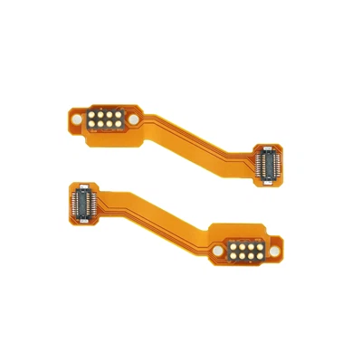
The display portion of a clock radio uses flexible connection circuits that often work abnormally. The main cause of this problem is poor connector quality. We propose to solve this problem by using PI films on flexible rigid PCBs.
For flexible circuits, such as those used in electronic devices, various materials such as PET, PI and glass fibre cores are used to protect the conductors. In addition, circuits may require the use of other protective films, such as those designed to prevent corrosion and damage. These can be used to shield against solder resist inks. In addition, insulating films help prevent conductor damage or corrosion.
PET and PI films are available in thick film thicknesses of approximately 1/3 to 3 mils. Other options for this film are glass fibre or epoxy resins, typically 2 to 4 mils thick.
Although FR4 materials are typically used in rigid boards, there are many requirements that must be considered when using them in conjunction with rigid-rigid bonding materials.
Polypropylene polyimide (PI) is highly flexible and temperature resistant and is often used for flexible substrates. Advantages include good mechanical and electrical properties, good moisture absorption and good weathering resistance.
Polyester PET is inexpensive and has good tear resistance, flexibility and mechanical properties. Unfortunately, the disadvantages of this material become apparent when heated, as shown below.
Significant shrinkage
Unsuitable for high-temperature welding due to its resistance to heat
Covers
The cover film on PCBs usually consists of polyimide, polyester or polyethylene. The film acts as a mechanical and environmental barrier to protect the copper surface from damage during assembly and handling. Depending on the application, the thickness of the protective layer ranges from 0.5 mils to 5 mils. Reinforcement film is used to cover Flex PCBs when soldering or the addition of reinforcement material is required, and can be made from a variety of materials such as aluminium, steel and FR4.
Low flow PP is commonly used to cover Flex Rigid Bond PCBs such as Flex-Connect and Rigid. Typically, this material is available in three sizes: 106 (2 mil), 1080 (3 mil), and 2116 (5 mil).
Overlay film is used to provide excellent mechanical and electrical protection. It is typically made of polyimide or polyester, which offers excellent heat resistance and high dielectric properties compared to PP. The thickness of this protective layer ranges from 0.5 mils to 5 mils. Most electronics typically used for money-saving activities, such as the printing of wires, are still made of copper wire. However, copper foil can be used in different forms when replacing wires and connectors. For example, if only connectors and wires are being replaced, copper foil may be the best choice.
Additionally, when increasing the carrying capacity of a device such as a conductor, copper foil can be used by increasing its weight. This material also allows for 1x copper sheet widths.
Finally, due to its high frequency properties, copper foil is often used to enhance the capabilities of insulating materials. This provides better shielding and reduces static interference. Copper foil can also be used as a protective layer between components due to its low resistance and high dielectric properties compared to PP. Unfortunately, copper is known to perform poorly in operation and causes stress and fatigue. If a flexible circuit needs to be moved or folded repeatedly to maintain its structural integrity, then copper foil may be the best choice. However, due to its rolling toughness, it can be bent and folded more frequently before fatigue fracture occurs.
The added flexibility of copper foil when rolled can also be used to improve its mechanical properties. For example, this material can extend the life of flexible circuits by increasing their rolling toughness.
Adhesives
In addition to copper foil, we must also apply adhesives to other films, such as PI films. Due to the different properties of copper foils, such as hardness, it is not possible to achieve a good bond under high pressure and temperature. Some manufacturers offer both double-sided and single-sided copper-clad laminates. They use epoxy or acrylic adhesives with a thickness of one to two mils or one mil. It was developed specifically for FPC. Due to the increasing popularity of 'adhesive-free' laminates, the need for more efficient processing techniques has led to the development of new materials, such as copper skins on PI films. These materials can be used for large-scale HDI circuits. When protecting Flex rigid joints, we will use hot melt adhesives, silicone or epoxy resins. These two materials will help to improve the mechanical strength of the joints and prevent them from stress fatigue.
Considerations for Flexible PCB Design Rules
Flexible Film Circuitry design is more complex than traditional printed circuit board design. This is why proper rules must follow all aspects of the design. For example, the transition areas of the board and wiring requirements follow the rules of the appropriate design rules.
 1. Through-hole locations
When flexible PCBs are bent in dynamic use, through-holes should be avoided wherever possible. These break easily and are usually the cause of damage. This means that when designing a flexible PCB, distances from the combined area should be avoided.
Design specifications for flexible rigid joint areas and through-hole regulations follow certain distances. For high performance applications, the limit is usually set around 70 mil. For fabricators, the through-hole limit should be at least 30mil. please follow the following rules for flex and vias. this is the most important rule for flex board assembly.
2. Design of pads and vias
Flexible PCBs need to be carefully considered when designing pads and vias. flexible PCBs are constructed from non-rigid substrate materials, usually polyimide or polyester, which allows them to bend and twist without breaking. However, this flexibility comes at a cost; as the material is not as rigid as traditional FR4 substrates, pads and vias require greater precision to ensure they can withstand bending.
Flexible PCBs often require unique pad shapes or sizes and special soldering techniques to maximise durability and performance. Extra spacing between components and circuits is also required to prevent short circuits due to strain on the board. These factors must be considered when designing a flexible PCB as they will determine the success of the final product. Engineers can produce reliable and efficient printed circuit boards by understanding the additional complexity involved in flexible PCBs and taking appropriate measures to ensure that all design elements are optimised for flexibility.
3. Routing Design
If there are multiple lines in the Flex area, try to avoid overlapping routes between the top and bottom layers of the copper board. It can lead to inconsistent stresses on the lines, which can lead to mechanical damage. Instead, the paths should be staggered and the top and bottom layers should be aligned in a straight line.
The design of a flexible area is similar to that of a rigid area, except that it should follow a circular arc instead of following a diagonal line. It will help protect the lines of the flexible board from being damaged when it is bent. Thick and thin lines should also be connected by tear-drop arcs to avoid sudden contraction or expansion.
4. Copper Laying Design
Some of you may be wondering, 'It is often better to use a mesh structure with a flat layer or layup of copper for flexible flex reinforced panels. Is this true? The answer is yes. However, for applications such as resistance control, the electrical quality of the mesh needs to be better. Therefore, designers should make an informed decision on the use of copper anilox. For example, if the waste area is covered with solid copper paving, the designer should consider designing stronger copper paving.
5. Distance between drilled holes and copper boards
Flexible printed circuit boards can accommodate a greater distance between the drilled holes and the copper board than traditional rigid boards. The flexible materials used in their construction allow for more complex designs and more detail. Therefore, it may be helpful to create designs that require more clearance or component space.
6. Flexible PCB Bending Area Bending Radius
The bend radius of a printed circuit board affects the overall performance and reliability of the PCB as it determines the amount of pressure applied to the components on the board.
Group Profile
ZHUHE Group has 10 subsidiaries, is a comprehensive service provider of electronic technology and electronic products, can provide customers with professional OEM / ODM services, the company's products and technologies show a diversity of products, covering semiconductor devices, pulse motors, high-frequency transformers, inductors, and a variety of electronic products, the core components PCBA (Printed Circuit Board Assembly) & FPCA (Flexible Printed Circuit Assembly) and other products, focusing on aerospace, military, industrial control, data communications, automotive electronics, medical electronics, new energy technology and AI smart technology. Assembly) & FPCA (Flexible Printed Circuit Assembly) and other products, focusing on aerospace, military, industrial control, data communications, automotive electronics, medical electronics, new energy technology and AI intelligent technology, the main markets at home and abroad, the core customers throughout: the United States, Japan, Germany and other domestic and foreign customers. Customers.

ZHUHE Group is positioned as an all-round EMS (Electronic Manufacturing Services) service provider, which can provide the industry with board design, component procurement, processing and manufacturing, and BGA, CSP, POP and other complex packaging device repair. Our products are designed and processed in a green way. The company's management standard, adhere to provide customers with quality products and services.

The company always adhere to the science and technology as the leader, market-oriented, technical innovation for the purpose of creating safe, efficient, portable backup power for the mission. Together we are committed to the development of solar backup power industry, and promote the application of green energy with high quality products and perfect service.

Q: What is the difference between flexible circuit board and rigid circuit board?
A: The biggest difference between flexible circuit board and rigid circuit board is its flexibility. The flexible circuit board uses flexible substrate materials, which can realize operations such as folding, bending, and bending, and can be used in occasions where ordinary PCBs are difficult to use, such as bendable screens, bendable LEDs, etc. On the other hand, the base material of rigid circuit boards is rigid glass fiber or polyester, and the board surface is rigid.
Q: What are the advantages and disadvantages of flexible circuit boards?
A: The flexible circuit board has many obvious advantages: firstly, it can greatly save space and save the user's space cost; Secondly, it can adapt to various shapes, providing a good solution for product designers and engineers, in addition, the reliability of flexible circuit boards has been greatly improved, the noise temperature coefficient is small, the transmission rate is high, and the signal interference and other problems can be effectively controlled. However, there are certain disadvantages, such as complex production and high cost, the need for professional production personnel to carry out production, and the need for multiprocess processing and assembly.
Q: What are the advantages of Flexible Film Circuitry?
A: (1) It has flexibility, which can achieve special plasticity such as bending, folding, and bending;
(2) The product is light and thin, and the thickness can be extremely thin;
(3) High reliability, high performance, high-density wiring;
(4) Environmentally friendly and energy-saving, more material-saving than traditional PCB boards;
(5) It is suitable for small size, narrow pitch and high density circuit applications.
Hot Tags: flexible film circuitry, China flexible film circuitry manufacturers, suppliers, factory, Flexible Printed Board, , Filter Coil Inductor, Relaxo Neck Massager, Flexible Printed Circuit Board, Flexible Fpc