


An Inductor Electronicis defined as a passive component used in most circuits to store energy in the form of magnetic energy when current flows through it. It is also known as a coil, choke, or reactor. It is a two-terminal electrical component characterized by inductance. Inductance is defined as the ratio of the rate of change of voltage to current.
Applications of Inductors
Inductors have various uses in power transmission according to their requirements.
1. Inductors for tuning circuits
With the help of inductors, tuned circuits can be selected for the desired frequency. Capacitor types are used along with inductors in various electronic devices such as radio-tuned circuits, and TVs to modify the frequency and help in selecting among multiple frequency channels.
2. These are used as sensors
Inductive proximity sensors are non-contact sensors that operate very reliably. Inductance is the main principle behind it wherein the magnetic field in the coil will be opposite to the flow of current. The proximity sensor mechanism is used in traffic signals to detect traffic density.
3. It is also used to store energy in devices
Inductors can store energy for a short period as the energy stored in the form of a magnetic field disappears when the power is removed. The use of inductors can be seen in computer circuits where the power supply can be switched.
4. Use of Inductors in Induction Motors
In an induction motor, the shaft in the motor rotates due to the presence of the magnetic field generated by the alternating current. The speed of the motor can be fixed according to the frequency of the power supply. The use of an inductor for motor speed can be controlled.
5. It is used as a transformer
The combination of multiple inductors with a shared magnetic field can be designed as a transformer. One of the major uses of transformers is in power transmission systems. These transformers are used to reduce or increase the transmission of power, as step-down or step-up transformers.
6. Inductors as Filters
Inductors are used as filters when combined with capacitors. The frequency of the input signal as it enters the circuit is limited by the use of these filters. As the frequency of the power supply increases, the impedance of the inductor increases.
7. Inductors in Chokes
As we know, when AC current flows through an inductor, it generates current in the opposite direction. This causes the inductor to block the AC current and pass the DC current. This mechanism is used to convert AC power to DC power.
8. Used as Ferrite Beads
We have seen ferrite beads used in computer components and cell phone charging cables. The inductors used in ferrite beads help in reducing the frequency of the radio interface generated by the cable.
9. These are used as relays
The relay behaves like an electrical switch. By using an inductive coil in the switch, a magnetic field is generated whenever the switch is in contact with AC current.
Operating Principles, Benefits and Applications of Surface Mount Inductors
Surface mount inductors play an important role in power electronics applications, but their importance is often overlooked or misunderstood. Specifically designed to store and release energy in circuits, these small coil-shaped components help regulate and control the flow of current. Whether in power supplies, motor drives, or other electronic devices, understanding the role of these components is critical for engineers and designers working in the power electronics field.
How SMD Inductors Work
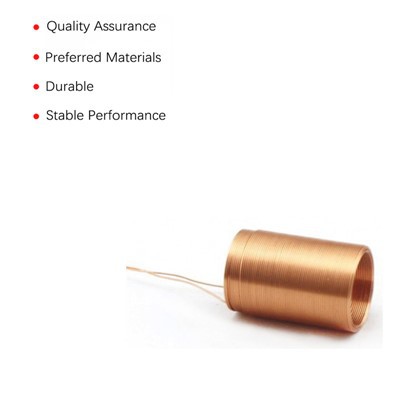
Surface mount inductors feature a coil of wire wrapped around a core material, which can be ferrite or ceramic. The core material plays an important role in enhancing the magnetic properties of the inductor, thereby improving performance and increasing inductance. Copper or other highly conductive materials are typically used for the wires in surface mount inductors. The main purpose behind these components is to store energy in their magnetic field.
When a DC current flows through a coil, a magnetic field is created. This magnetic field opposes any changes that occur in the current, effectively storing energy within the inductor. When the current stops or undergoes a rapid change, the stored energy is released in the form of an electromagnetic field. This phenomenon makes surface mount inductors essential in smoothing out current fluctuations, filtering out unwanted signals, and improving the stability of electronic circuits.
Advantages of Surface Mount Inductors
Surface mount inductors offer several advantages that make them a popular choice for a variety of electronic applications. Some of these include.
Space-saving design: Inductor Electronics are compact and have a flat profile, a design that allows for efficient use of space in many advanced electronic applications.
Improved Performance: SMD inductors offer low resistance and high inductance, making them ideal for applications that require high performance and stable operation. They are designed to provide excellent signal integrity and reduce noise interference, thus improving overall system performance.
Higher Reliability: They can withstand challenging environmental conditions, including varying temperature ranges, vibration, and shock. As a result, they exhibit excellent reliability and ensure optimal performance over time.
Compatibility with modern technologies: These inductors are ideally suited for integration into modern electronic devices such as smartphones, tablets, wearables, and IoT devices. Their compatibility with surface mount technology and automated assembly processes makes them a popular choice for a variety of applications.
Customization options: SMD inductors are available in a wide range of sizes, inductance values, and package types. This flexibility ensures compatibility with a variety of design constraints and ease of customization to meet specific application requirements.
Typical Application Areas
The applications for SMD inductors are endless. Some of them include;; Telecommunications and wireless communication systems.
Telecommunications and wireless communication systems: radio frequency (RF) circuits, smartphones and tablets, etc.
Medical: monitoring and diagnostic devices, implantable devices, medical imaging, life support systems, and wearable medical devices.
Power Electronics. Power converters, voltage regulators, and other power management systems.
Automotive: engine control units, infotainment systems, and advanced driver assistance systems (ADAS).
Consumer electronics: audio/video equipment, game consoles, audio amplifiers, filters, and signal processing circuits.
Precision Noise Suppression with Common Mode Chokes
Common mode chokes (CMCs) are not only a key component in electrical engineering, but they are also essential. They play a key role in mitigating electromagnetic interference (EMI) and ensuring signal integrity in power and communication systems.
What is a Common Mode Choke?
A common mode choke (CMC) is an inductor that blocks high-frequency noise signals affecting both wires. It allows normal signals to pass through. This feature is critical to reducing EMI in power and data lines. Typically, engineers use CMCs in switching power supplies, signal lines, and data transmission cables.
Types of Common Mode Chokes
Common mode chokes come in a variety of shapes and configurations to meet different application requirements:
Ring CMC: These are donut-shaped and provide efficient magnetic coupling.
Bar Core CMC: Cylindrical in shape, typically used in compact designs.
Flat CMC: Flat and compact, suitable for surface mount technology (SMT).
Split Core CMC: Designed for easy installation around existing cables.
The choice of core material (ferrite, nanocrystalline, amorphous) and winding configuration (double-stranded, multi-stranded) directly affects the performance of the CMC in terms of inductance, frequency response, and saturation characteristics.
 Selection Criteria for Power Applications
There are several key factors involved in selecting a CMC for a power supply application:
Impedance: The impedance at the target noise frequency should be high enough to effectively attenuate the noise.
Current Rating: The CMC must handle the maximum operating current without saturating.
Temperature Stability: The core material should maintain performance over the operating temperature range.
Size and Form Factor: The physical dimensions shall conform to the design constraints of the power supply unit.
Principle of Operation of Common Mode Chokes
A CMC operates by generating opposing magnetic fields in its windings when a common mode current flows through it. These opposing magnetic fields cancel out the common mode noise. These magnetic fields do not cancel out the differential mode currents, allowing these signals to pass through with minimal attenuation.
Winding and Core Materials
The winding technology and core material of a CMC can seriously affect performance:
Winding Configuration: Proper winding ensures maximum impedance and minimum leakage inductance. Techniques such as double-wire winding improve performance by reducing parasitic capacitance.
Commonly used core materials include ferrite, powdered iron, and nanocrystalline materials. Each material offers different permeability and saturation characteristics that affect the efficiency and size of the choke.
Differences between CMC, Transformer, and Ferrite Beads
- CMC vs. Transformer: A CMC filters noise while a transformer transfers energy between circuits. Transformers have separate primary and secondary windings, while CMCs have a single core whose windings share a common path of magnetic flux.
- CMC vs. Ferrite Beads: Ferrite beads are simpler devices used to suppress high-frequency noise on signal lines. They have lower impedance than CMCs and are not suitable for high-current applications.
Common Mode Noise
Common mode noise comes from external electromagnetic sources or internal circuit imbalances. It induces unwanted signals in the communication lines and degrades system performance. CMCs mitigate this by providing a high-impedance path for common mode signals, thus attenuating the noise.
Differential Mode in CMC
In differential mode, current flows through the choke winding in the opposite direction, thus canceling out the magnetic field. This allows differential signals to pass through with minimal loss.
A differential mode signal is the desired signal for transferring information between two lines. In a well-designed CMC, the differential-mode signal passes through unattenuated, while the common mode signal is blocked, ensuring clean and efficient signal transmission.
Common Mode Choke Uses
CMCs are used in a variety of applications:
- Power supplies: Filter EMI and ensure stable power delivery.
- Data Lines: Prevents data corruption and ensures signal integrity.
- Telecommunication Systems: Reduces noise in communication lines.
- Automotive electronics: Suppresses noise in-vehicle electronic systems.
Data Line and Power Line CMC
- Data Line CMC: Designed to handle lower currents and higher frequencies, focusing on minimal signal loss and high impedance at operating frequencies.
- Power Line CMC: Designed to handle higher currents with larger core sizes and materials that can withstand high power dissipation.
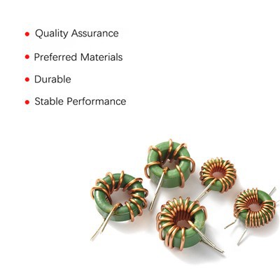
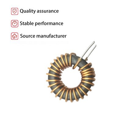
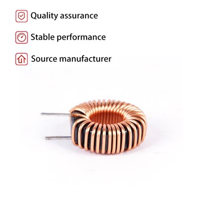
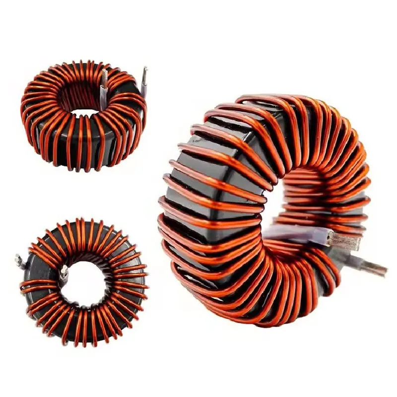
CMT Type Toroidal CMC
CMT (Common Mode Toroidal) type toroids are widely used in CMC designs for their efficient magnetic coupling, low EMI and compact form factor.
They are made by wrapping metal wires around a donut-shaped core, which makes them small and reduces energy losses.
The shape/geometry of the toroidal coil reduces leakage inductance. It also helps to eliminate common mode noise in the magnetic field generated by the winding.
Their excellent magnetic properties and efficiency make them widely used in power and RF applications.
Some rich insights from the technical study
Leakage Inductance Estimation in Toroidal CMCs
Leakage inductance in toroidal CMCs is a key parameter that affects the overall performance of the choke. It is affected by core material, winding technology, and physical separation between windings. To accurately estimate leakage inductance, use advanced simulation models. These models should take into account the core shape and magnetic properties of the material.
Magnetoresistive and Capacitive Analogies
The analogy between magnetoresistance and capacitance provides a useful framework for understanding the magnetic behavior of CMCs. Just as capacitance in a circuit opposes changes in voltage, magnetoresistance in a magnetic circuit opposes changes in flux. This analogy helps in designing CMCs with optimal magnetic properties to achieve the desired level of noise attenuation.
Group Profile
ZHUHE Group has 10 subsidiaries, is a comprehensive service provider of electronic technology and electronic products, and can provide customers with professional OEM / ODM services, the company's products and technologies show a diversity of products, covering semiconductor devices, pulse motors, high-frequency transformers, inductors, and a variety of electronic products, the core components PCBA (Printed Circuit Board Assembly) & FPCA (Flexible Printed Circuit Assembly) and other products, specializing in aerospace, military, industrial control, data communications, automotive electronics, medical electronics, new energy technology, and AI smart technology. Assembly) & FPCA (Flexible Printed Circuit Assembly) products, focusing on aerospace, military, industrial control, data communications, automotive electronics, medical electronics, new energy technology, and AI intelligent technology, the main markets at home and abroad, the core customers throughout the United States, Japan, Germany, and other domestic and foreign customers. Our core customers are in the United States, Japan, Germany, and other domestic and foreign customers.

The company has a strong R & D team and professional automated production lines, and gradually introduced advanced production equipment and increased investment in the automation of production lines, to improve production capacity and manufacturing process level, and established a perfect quality management system and supply chain system; to provide the best quality intelligent control solutions and products.

We always adhere to science and technology as the leading, market-oriented, technological innovation for technological innovation and value enhancement for the mission. Together we are committed to the development of electronic technology and new energy industry and promote the application of green energy with high-quality products and perfect service.

Q: What are the factors that affect Inductor Electronic?
1. The number of turns in the coil
When the number of turns in the coil is larger, electricity
The greater the feeling,. The more coils, the greater the magnetic field force representing a given coil current.
2. Coil area
The inductance is directly proportional to the coil area. The larger the coil area, the greater the inductance. For a given magnetic force, the larger the coil area, the less resistance is formed to the magnetic field flux
3. Core material
The greater the permeability of the coil-wound core, the greater the inductance.
4. Coil length
The longer the coil length, the smaller the inductance. The shorter the coil length, the greater the inductance.
Q: Why can inductor coils be used for filtering?
A: The inductor coil can be used for filtering because in AC circuits, the impedance of the inductor coil changes with the change of frequency, and in a certain frequency range, the impedance of the inductor coil can reach a very high value, thus forming a low-pass filter.
Q: Is there a relationship between the impedance and frequency of the common mode choke toroid?
A: The impedance of the inductor coil is positively correlated with the frequency of the current inside it, and when the frequency increases, the impedance of the inductor coil also increases. This is because, at higher frequencies, the current in the coil does not change fast enough, resulting in the magnetic flux inside it not changing in time, hence the repulsion effect.
Hot Tags: inductor electronic, China inductor electronic manufacturers, suppliers, factory, Insulated Gate Bipolar Transistor Igbt, Flexible Fpc, Electric Generator Stator, Square Cabin Mobile Phone Sterilizer, Power Supply, Samsung Mobile Phone Wireless Charger