As a seasoned provider of inductance coils, I've witnessed firsthand the pivotal role these components play in DC - DC converters. In this blog, I'll delve into how an inductance coil performs in a DC - DC converter, exploring its fundamental principles, functions, and real - world implications.
Basic Principles of Inductance Coils in DC - DC Converters
An inductance coil, also known as an inductor, is a passive two - terminal electrical component that stores energy in a magnetic field when electric current flows through it. In a DC - DC converter, which is a circuit that converts one DC voltage level to another, the inductance coil is a key element.
The operation of an inductance coil in a DC - DC converter is based on Faraday's law of electromagnetic induction. When the current through an inductor changes, it induces an electromotive force (EMF) across the inductor according to the formula (e = - L\frac{di}{dt}), where (e) is the induced EMF, (L) is the inductance of the coil, and (\frac{di}{dt}) is the rate of change of current.
In a DC - DC converter, the power switch (usually a MOSFET) is used to control the current flow through the inductor. When the switch is closed, current starts to flow through the inductor, and the inductor stores energy in its magnetic field. The current in the inductor increases linearly over time, as described by the equation (i=\frac{V}{L}t), where (V) is the voltage across the inductor and (t) is the time.
When the switch is opened, the magnetic field in the inductor collapses. According to Lenz's law, the inductor tries to maintain the current flow, and it generates a voltage to push the current in the same direction. This energy stored in the inductor is then transferred to the output of the DC - DC converter, either to charge a capacitor or to supply power to the load.
Functions of Inductance Coils in Different Types of DC - DC Converters
Buck Converters
A buck converter is used to step - down a DC voltage. In a buck converter, the inductor is connected in series between the input voltage source and the output load. When the power switch is on, the input voltage is applied across the inductor, and the inductor current increases. The energy is stored in the inductor's magnetic field.
When the switch is off, the inductor current continues to flow through the free - wheeling diode to the output. The inductor releases its stored energy to the output, maintaining the current flow to the load. The output voltage of a buck converter is given by (V_{out}=D\times V_{in}), where (D) is the duty cycle of the power switch ((D = \frac{t_{on}}{t_{on}+t_{off}})), (V_{in}) is the input voltage, and (V_{out}) is the output voltage. The inductor in a buck converter helps to smooth the output current and reduces the ripple voltage at the output.
Boost Converters
A boost converter is used to step - up a DC voltage. In a boost converter, the inductor is connected in series with the input voltage source. When the power switch is on, the input voltage is applied across the inductor, and the inductor current increases, storing energy in the magnetic field.
When the switch is off, the inductor current cannot change instantaneously. The inductor voltage reverses, and the sum of the input voltage and the inductor voltage is applied across the output capacitor and the load. The output voltage of a boost converter is given by (V_{out}=\frac{V_{in}}{1 - D}). The inductor in a boost converter plays a crucial role in storing energy during the switch - on period and then transferring it to the output during the switch - off period, enabling the voltage step - up operation.
Buck - Boost Converters
A buck - boost converter can either step - down or step - up the input voltage. It has a more complex configuration compared to buck and boost converters. The inductor stores energy when the power switch is on and releases it to the output when the switch is off. The output voltage can be either higher or lower than the input voltage, depending on the duty cycle of the switch. The output voltage of a buck - boost converter is given by (V_{out}=-\frac{D}{1 - D}V_{in}). The negative sign indicates that the output voltage has an opposite polarity compared to the input voltage.
Factors Affecting the Performance of Inductance Coils in DC - DC Converters
Inductance Value
The inductance value (L) of the coil is a critical parameter. A larger inductance value results in a smaller ripple current in the inductor, which leads to a smoother output current and lower ripple voltage at the output of the DC - DC converter. However, a very large inductance value may increase the size and cost of the inductor and also slow down the transient response of the converter.
DC Resistance (DCR)
The DC resistance of the inductor causes power losses in the form of (I^{2}R) losses, where (I) is the average current flowing through the inductor and (R) is the DCR. Lower DCR is desirable to minimize power losses and improve the efficiency of the DC - DC converter.
Saturation Current
The saturation current (I_{sat}) of an inductor is the maximum current at which the inductor's core starts to saturate. When the core saturates, the inductance value drops significantly, which can lead to increased ripple current, reduced efficiency, and even damage to the converter components. Therefore, it is important to select an inductor with a saturation current higher than the maximum expected current in the DC - DC converter.
Frequency Response
The performance of an inductor in a DC - DC converter is also affected by the switching frequency of the converter. Higher switching frequencies allow for smaller inductors, as the energy storage and transfer cycles are shorter. However, higher frequencies may also increase the switching losses in the power switch and the core losses in the inductor.
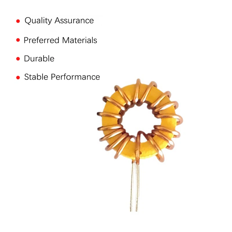
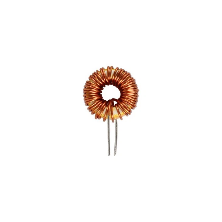
Our Inductance Coil Offerings
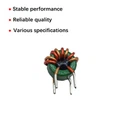
As an inductance coil supplier, we offer a wide range of products to meet the diverse needs of DC - DC converter applications. Our Inductor Coil Winding products are carefully designed and manufactured to ensure high - quality performance. We use advanced winding techniques to achieve precise inductance values and low DCR.
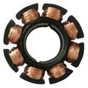
Our Torrid Coil series provides excellent magnetic coupling and high saturation current capabilities. These coils are suitable for high - power DC - DC converters where large amounts of energy need to be stored and transferred.
The Common Mode Choke Toroid in our product portfolio is ideal for suppressing common - mode noise in DC - DC converters. It helps to improve the electromagnetic compatibility (EMC) of the converter and ensures reliable operation in noisy environments.
Conclusion and Call to Action
In conclusion, inductance coils are essential components in DC - DC converters, playing a vital role in energy storage, voltage conversion, and current smoothing. Understanding how inductance coils perform in DC - DC converters is crucial for designing efficient and reliable power conversion circuits.
If you are looking for high - quality inductance coils for your DC - DC converter applications, we are here to help. Our team of experts can provide you with technical support and guidance to select the most suitable inductance coils for your specific requirements. Contact us today to start a procurement discussion and take your DC - DC converter designs to the next level.
References
- Erickson, Robert W., and Dragan Maksimović. Fundamentals of Power Electronics. Springer, 2001.
- Pressman, Abraham I. Switching Power Supply Design. McGraw - Hill, 1998.
- Mohan, Ned, Tore M. Undeland, and William P. Robbins. Power Electronics: Converters, Applications, and Design. Wiley, 2012.